
|
Gtek International Co., Limited
|
Application Q&A
11. Is it possible to run into EMI problems when using MW LED power supply? How to go about solving such problems?
Independent external type (metal/plastic enclosure):
EMI test setup consists of isolated power supply and LED load. The EMI test report has data for both EN55015/EN55022. For Class I units with FG wire available, it is recommended to have both the power supply FG wire and lamp chassis connected to Earth ground. This can reduce overall EMI noise. Depending on actual application, the input and output cables can be several meters long and this can lead to high common mode noise. If this is the case, we recommend adding common mode choke as close to the lamp head as possible. The same can also be done for AC input cable (refer to diagram 8).

Figure 8: Surge & EMI countermeasure
Built-in PCB/U bracket:
For PLP/ULP Series, its design is based on being mounted on the same metal plane as the LED module. The EMI test setup is as shown below in figure 6. An iron plate is used to simulate metal chassis. The output cable length will vary depending on system setup and this will have big effect on the EMI. For this reason, we recommend twisting the output cable and adding clamp on core to reduce EMI noise.
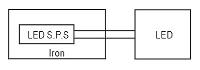
Figure 6: EMI setup for PCB & U type products
LED module with driver IC:
The previous EMC suggestions may not be as effective when it comes to designs with LED driver IC. EMI solution will be more complicated due to the fact that the LED driver IC itself also switches at high frequency (few hundred kHz ~ MHz). For this reason, the driver IC must have internal noise filter. Special attention should be paid to IC ground layout and placement of input and output capacitors and inductors. General suggestion is shown in figure 7. Common mode choke and high frequency X capacitor must be incorporated in between the power supply and LED driver PCB.

Figure 7: EMI solution for system with LED driver IC
Independent external type (metal/plastic enclosure):
EMI test setup consists of isolated power supply and LED load. The EMI test report has data for both EN55015/EN55022. For Class I units with FG wire available, it is recommended to have both the power supply FG wire and lamp chassis connected to Earth ground. This can reduce overall EMI noise. Depending on actual application, the input and output cables can be several meters long and this can lead to high common mode noise. If this is the case, we recommend adding common mode choke as close to the lamp head as possible. The same can also be done for AC input cable (refer to diagram 8).
Figure 8: Surge & EMI countermeasure
Built-in PCB/U bracket:
For PLP/ULP Series, its design is based on being mounted on the same metal plane as the LED module. The EMI test setup is as shown below in figure 6. An iron plate is used to simulate metal chassis. The output cable length will vary depending on system setup and this will have big effect on the EMI. For this reason, we recommend twisting the output cable and adding clamp on core to reduce EMI noise.
Figure 6: EMI setup for PCB & U type products
LED module with driver IC:
The previous EMC suggestions may not be as effective when it comes to designs with LED driver IC. EMI solution will be more complicated due to the fact that the LED driver IC itself also switches at high frequency (few hundred kHz ~ MHz). For this reason, the driver IC must have internal noise filter. Special attention should be paid to IC ground layout and placement of input and output capacitors and inductors. General suggestion is shown in figure 7. Common mode choke and high frequency X capacitor must be incorporated in between the power supply and LED driver PCB.
Figure 7: EMI solution for system with LED driver IC
.gif)
